- Home
- About Us
- Cooper Gensets
- Services
- Exhaust Piping, Cladding, MS strucutire design and fabrication
- Design and supply of HT LT PCC and MCC panel
- HT LT cabling work
- Design and installation of piping projects and construction of diesel yard for diesel stock in high volume
- PESO Lincense for disel storage/ explosive
- Design Installation of Internal House wiring, garden and showrooms
- Supply & Installation of Industrial shed wiring / Building wiring
- Automation in fuel supply and piping heat insulation
- Allied Civil work Activity
- Concertina coil compound
- Project
- Contact Us
HOME< INSTALLATION OF DG SET, EXHAUST STACK & PIPE SYSTEM AND FOUNDATION
INSTALLATION OF DG SET, EXHAUST STACK & PIPE SYSTEM AND FOUNDATION
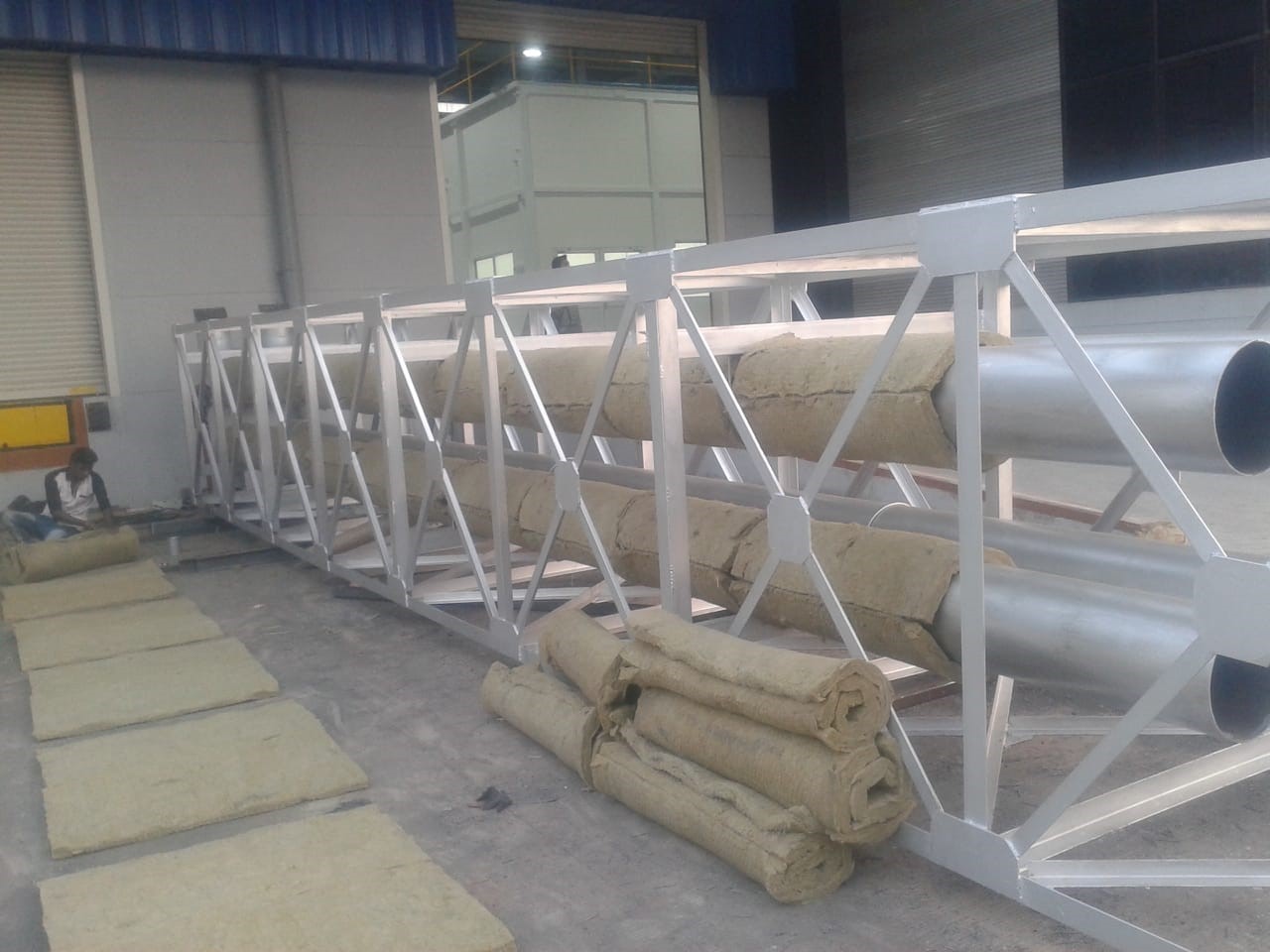
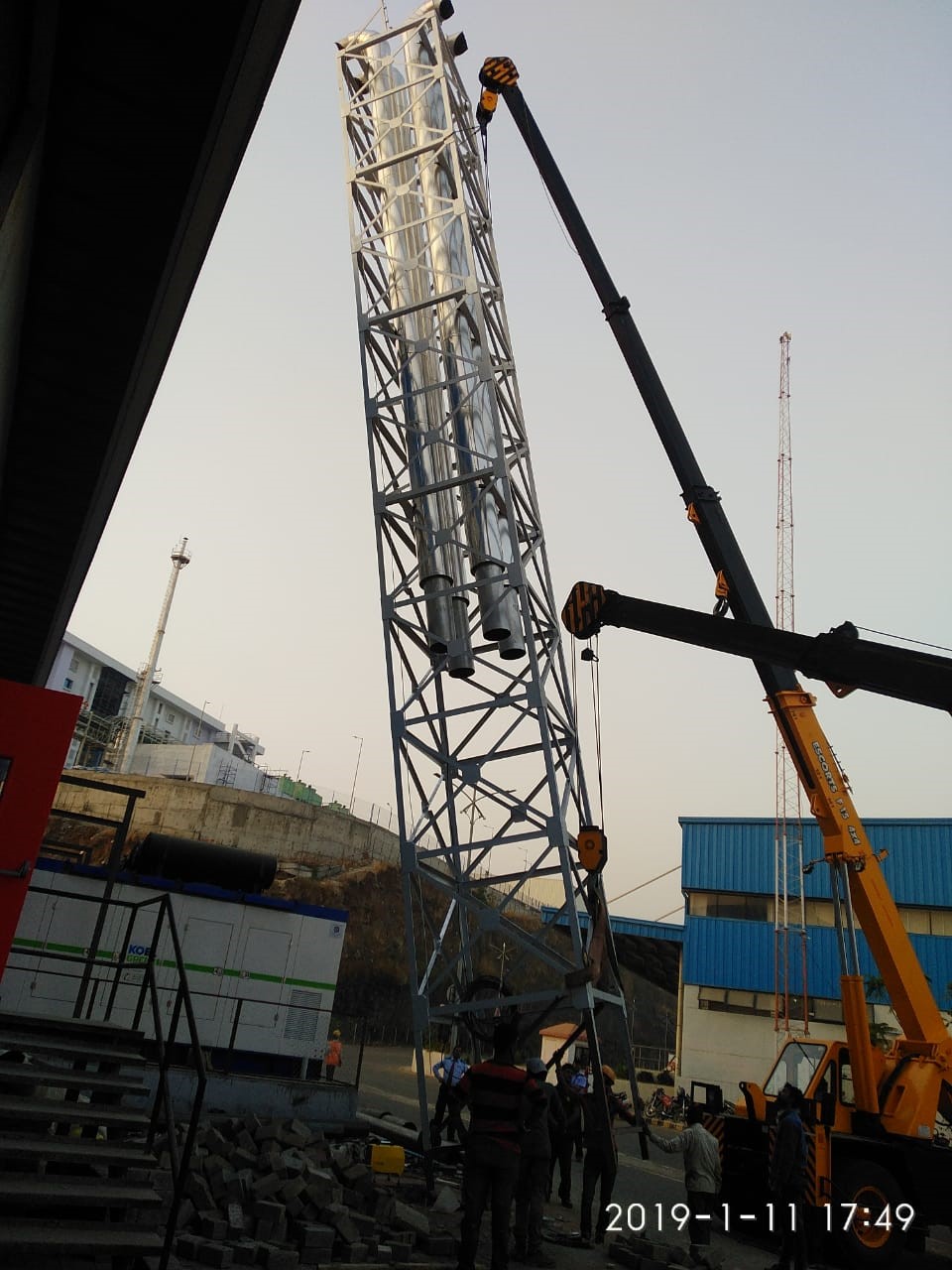
Design, supply and installation of Exhaust pipe with stack up to 40 meters with suitable thickness cladding.
Rain protection to be provided for exhaust ducting like, 90 deg. bend with bird mesh, cowl or special diffuser. It is recommended that horizontal run of exhaust piping should slope downwards away from the engine. Condensate drain pipe to be provided in horizontal ducting after silencer to avoid rain water entry or condensate entry to engine.
Silencer Location: Locating the silencer close to the Engine improves the sound attenuation.


Exhaust stack height: In order to dispose exhaust above building height, minimum exhaust stack height should be, as per latest CPCB/ local pollution control board norms.
For DG set below 1000 kVA H = h + 0.2 x √kVA
Where H = height of exhaust stack h = height of building.
- For DG set above 1000 kVA – Minimum 30 meter
- In case building height is more than 30 meter Stack Height = Building height + minimum 6 meter.
- Note: Exhaust stack height should be considered of maximum value of the above.
- Recommended scheme for ‘Y’ piece construction for two banks duct connections:- Exhaust of two banks of V engines can be connected before/after silencer. Ensure that the common duct diameter is calculated considering the backpressure and velocity criteria.
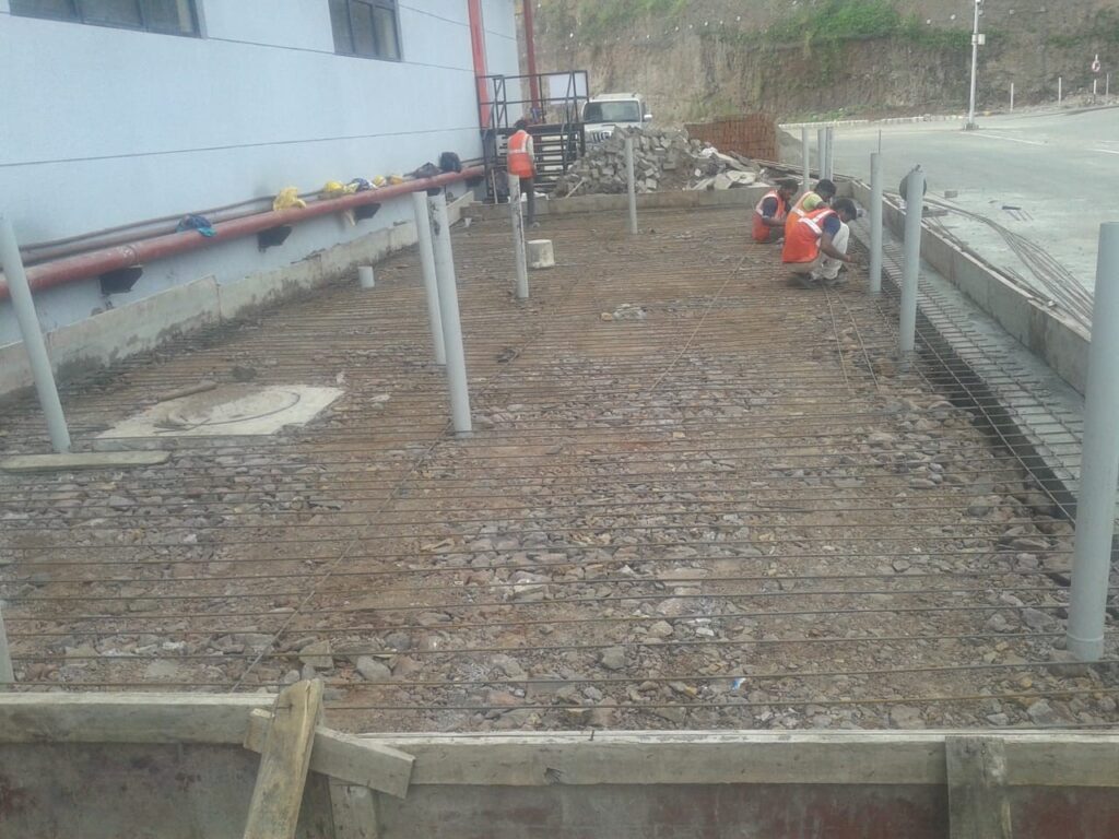
Foundation should be designed considering safe bearing capacity of soil and DG set static and dynamic load. Anti-Vibration Mounts (AVMs) are provided to reduce generator set vibration and noise transmission to the surrounding structure. The depth of the foundation to be decided by the customer in consultation with the certified structural engineer depending on static and dynamic load of the DG set and soil condition. Contact GOEM for static and dynamic load data of the DG Set. The length and breadth of foundation should be minimum 150 mm (6”) more than acoustic enclosure size / base rails size. Ensure that the concrete is completely set and hardened before positioning the generator set.


It is recommended to have foundation elevation 150 mm above finish ground level. It helps to maintain cleanliness of DG Set. For areas having heavy rainfall, a higher platform/ rain shed (not mandatory) may be required to prevent water entry and it also helps in operator’s safety.


